Metering units

Measuring installations

Measurement of well production: units based on multiphase flow meters and separation-type units. Stationary and mobile design.

2 typesmultiphase flow meters and separation-type units
up to 34.5 MPamaximum pressure in the pipeline
−20…+130 °Ctemperature of the measured medium
Description and purpose

Description and purpose

The metering units are designed to measure the mass flow rate and mass of crude oil, the volumetric flow rate and volume of associated petroleum gas reduced to standard conditions, and the mass flow rate and mass of separated oil excluding water, produced from wells (a group of wells), as well as to display, archive and transmit measurement results and alarm signals to the oilfield dispatch centre for field surface facilities or to an engineering station (for a mobile metering unit).

Metering units based on multiphase flow meters are manufactured to TU 28.99.39-011-88090790-2023 and can be either stationary or mobile.

Separation-type metering units are manufactured to TU 28.99.39-011-88090790-2023

Both types of metering units can be of mobile (based on a trailer or self-propelled chassis) or stationary design.

The choice of the metering unit modification is based on the Customer's needs, taking into account the operational specifics of the facility or well (group of wells) and the possible advantages of a particular type of unit.

  • Mass flow rate and mass of crude oil
  • Volumetric flow rate and volume of associated petroleum gas reduced to standard conditions
  • Mass flow rate and mass of separated oil excluding water
  • Manufactured to TU 28.99.39-011-88090790-2023
  • Stationary and mobile design: trailer or self-propelled chassis
Specifications

Technical specifications

Using a mobile separation-free metering unit as an example.

Technical specifications
Measured parametersValue
Flow meter installation methodVertical with upward flow
Measured mediumOil / water / gas
Nominal diameterFrom 50.8 mm to 203.2 mm (from 2" to 8")
Size/internal diameter4/50, 4/67, 6/87, 8/132, 10/173 in/mm
Gas volume fraction in the flow (GVF)from 0 to 100%
Viscosity of the measured mediumAny
Density of the measured mediumNot more than 1,200 kg/m³
Maximum pressure in the pipelineNot more than 34.5 MPa
Temperature of the measured mediumFrom -20 to +130 ºC
Communication interfaceRS-232/RS-485/Ethernet
Data exchange protocolModbus ASCII/RTU/TCP
Permissible relative error of measurements of the mass and mass flow rate of crude oil at a gas volume fraction of 0% to 90%Not more than 2.5%

Metrological characteristics

Metrological characteristics
Permissible relative error of measurements of the mass and mass flow rate of crude oil excluding waterValue
At a water volume fraction in crude oil not exceeding 70%Not more than 6%
At a water volume fraction in crude oil from 70% to 95%Not more than 15%
Permissible relative error of measurements of the volume of associated petroleum gas reduced to standard conditions at a gas volume fraction from 25% to 100%Not more than 5%
Scope of supply

Scope of supply and equipment layout

Using a mobile separation-free metering unit as an example. As standard, the unit consists of a process skid and an instrumentation skid.

Process skid

What is located in the process skid

The process skid is designed to house the measuring instruments and process equipment included in the unit and to provide conditions for their normal operation. For example, the skid can be made as an insulated enclosure, inside which the following are installed:

  • Roxar MPFM 2600 multiphase flow meter (Roxar MPFM 2600, Pietro Fiorentine or other imported and domestic equivalents)
  • Safety valve
  • Check valve
  • Main piping used to connect the unit inlets to the flow meter inlet and the flow meter outlet line to the outlet manifold
  • Drain piping
  • Hydraulic power unit
  • Chemical reagent tank
  • Dosing pump
  • Shut-off and control valves
  • Instrumentation and control devices
  • Fire alarm and gas detection sensors
  • Other process equipment depending on project requirements
Instrumentation room

What is located in the instrumentation room

The instrumentation room is designed as an insulated enclosure housing:

  • Flow computer (or the flow meter electronic computing unit / measuring and computing system)
  • Power cabinet and control cabinet (if provided)
  • Secondary fire alarm devices and gas analyzers are installed

An electric heater is installed to maintain the required positive temperature in the room. If required, a diesel generator set with a fuel storage tank can be optionally installed.

* The flow computer is a computing unit for fast execution of all flow parameter calculation algorithms. It communicates with all internal measuring instruments and interacts with the flow meter maintenance software and customer systems. This minimizes the number of metrologically significant elements of the unit, eliminating the need for additional computing units and controllers.
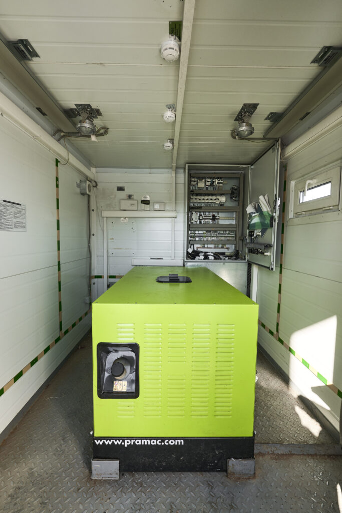
Example layout of an instrumentation room with a power cabinet and a standalone electric generator on a mobile chassis
Example layout of an instrumentation room with a power cabinet and a standalone electric generator, mounted on a mobile chassis.
Advantages

Key advantages and capabilities

Key advantages and capabilities of metering units based on multiphase flow meters:

  • Measurement of fluid phase flow rates under challenging flow conditions (viscous oil, slug flow, emulsions, low temperatures, foaming)
  • No impact of changes in the well operating mode on measurement accuracy
  • Accurate real-time measurement of phase quantities without flow separation
  • Bringing the well to the optimal production mode without waiting for stationary metering systems to be commissioned
  • Elimination of failure risks of stationary separation-type well test units
  • Minimizing the risk of production losses with minimal operating personnel presence for unit servicing (two persons)
  • Elimination of lengthy procedures of raw material preparation and measurement, reducing the labor intensity of measurements
  • Continuous real-time multiphase flow measurement across the entire well production rate range
  • Capability to determine the H2S fraction in the gas-liquid flow
  • Reliability and compactness
Separation unit

Separation metering unit

The separation metering unit consists of a process skid and a control and management unit and includes a set of installation and spare parts, a set of life support equipment, tools and accessories.

The process skid of the separation metering unit is designed to separate the production of an oil well into liquid and gas phases, measure the flow rate and quantity of each phase, control the operating mode of the separation vessel (SV) and operate the shut-off and control valves, to ensure normal operating conditions for the process equipment, measuring instruments and life support system installed in it.

The metering unit (Type C) includes:
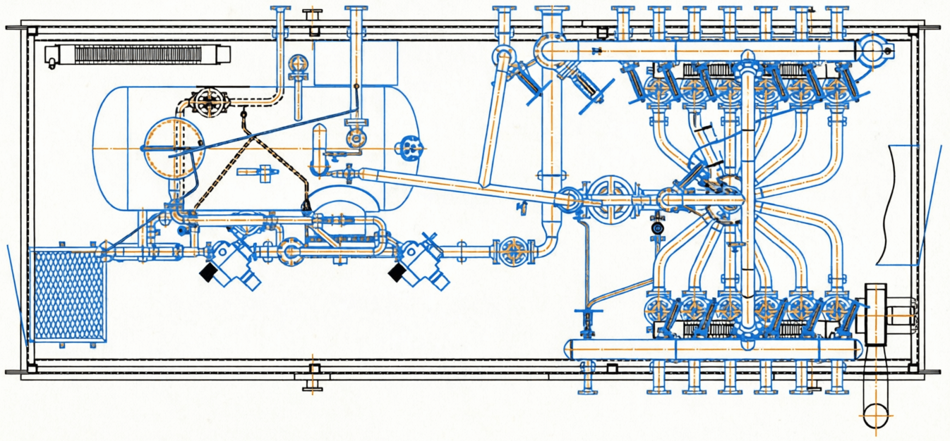
  • separation vessel (SV)
  • well selector (WS) with anti-corrosion protection of the inner surface and piping designed to alternately connect one of the wells to the SV and the others to the outlet manifold (not supplied when ordered with a single inlet)
  • GP-1M hydraulic actuator (not supplied when ordered with a single inlet)
  • liquid and gas filters (at the Customer's request)
  • piping designed to connect the gas and liquid outlets of the SV to the outlet manifold and the SV inlet to the WS
  • process and metering lines
  • bypass line
  • drain line and relief line from the pressure relief valve
  • shut-off and control valves
  • check valves complete with sealing elements, mating flanges and fasteners
  • measuring instruments (flow meters, pressure and temperature sensors)
  • moisture meter (optional)
  • indicating pressure gauges and thermometers on the process lines
  • samplers on the gas and liquid metering lines
  • life support system (heating, lighting and ventilation)
  • gas detection and alarm system
  • fire alarm system
  • security alarm system.
Layout of the separation metering unit
Examples

Examples

Mobile metering units on different chassis and with different flow meters — swipe the slides.

Example 1: Mobile metering unit with Roxar MPFM 2600 multiphase flow meter on a KAMAZ chassis

Instrumentation room
  • Flow computer
  • Power cabinet
  • Control cabinet
  • UPS
  • Rest area
Process room
  • Multiphase flow meter Roxar MPFM 2600
  • Working line and bypass line DN80
  • Pressure gauges
  • Gas detectors
  • Fire detectors
Previous
Next

Example 2: Mobile metering unit with Roxar MPFM 2600 multiphase flow meter on a tractor chassis

Previous
Next

Example 3: Mobile metering unit with SPMF-P multiphase flow meter

Previous
Next

Example 4: Mobile metering unit with Roxar MPFM 2600 multiphase flow meter. Transportation — using the Customer's transport.

Example 5: Mobile separation metering unit for a single well.

Need a metering unit for your project?

We will select the unit type for your flow rate and site conditions and send a quotation.