
Pipe prover unit PE-Prover-EXPERT
On-site verification and calibration of volumetric and mass liquid meters and flow transmitters. Stationary and mobile versions.
Pipe prover
The bidirectional pipe prover unit «PE-Prover-EXPERT» (hereinafter referred to as the pipe prover) is intended for on-site verification of volumetric and mass liquid meters and flow transmitters. The working medium can be crude oil, petroleum products, petrochemical products, gas condensate, water and other liquids. The operating principle is based on repeated displacement of a known volume of liquid from the pipe prover measuring section.
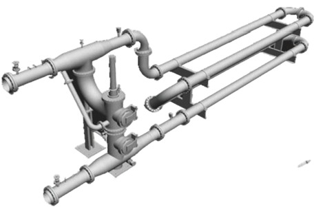
The pipe prover consists of the following main parts: a cylindrical section with the measuring volume, a spherical piston that moves freely under the action of the liquid flow, piston position detectors, a four-way switching and manipulating valve, and pressure and temperature measuring instruments.
When the liquid volume unit is transferred, the pipe prover and the flow transmitter are connected in series. The four-way switching valve of the pipe prover is turned to the "launch" position, and the liquid flow passing through the pipe prover starts the spherical piston. The movement of the piston through the pipe prover measuring section of known capacity causes the pipe prover detectors to actuate in sequence.
The pipe prover can operate together with a measuring and computing complex (hereinafter referred to as the IVK) or a pulse counter. The transfer of the liquid volume unit from the pipe prover to flow transmitters is determined by the correspondence between the number of pulses received from the flow transmitter and the volume of liquid displaced from the pipe prover. Actuation of the pipe prover detectors starts and stops the IVK or the pulse counter operating together with the pipe prover. In this case, the IVK counts the pulses coming from the transmitter being verified. Using the known capacity of the pipe prover measuring section and the number of pulses, the K-factor of the transmitter for the 1-3-1 and 2-4-2 paths is determined.
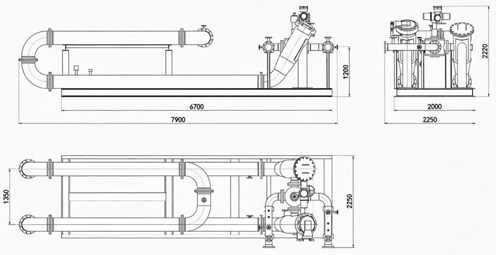
- Standard volume: 2 m³ (double pass)
- Nominal diameter: DN 300
- Nominal pressure: PN 1.6
- Flow rate range: 15…300 m³/h
- Dry weight: not more than 6000 kg
- Dimensions (L×W×H): 7.9×2.25×2.22 m
Solutions for high-accuracy verification and calibration across all application areas
The PE-Prover-EXPERT pipe prover units (hereinafter — the prover) are intended for measurement, reproduction, storage and transfer of the unit of liquid volume in flow during research, testing, verification, calibration and other works on determining the metrological characteristics of measuring instruments and standards of liquid volume units in flow and/or volumetric liquid flow, as well as measuring instruments of liquid mass in flow and/or liquid mass flow included in systems for measurement of quantity and quality parameters of liquids.
The operating principle of the prover is based on repeated displacement by a spherical piston of a known liquid volume from the measuring section limited by detectors. The spherical piston moves forward under the action of the liquid flow passing through the prover measuring section.
Depending on the implemented process scheme, the prover may have either unidirectional or bidirectional movement of the spherical piston along the calibrated section. In the bidirectional version, the return of the spherical piston is performed along the calibrated section by reversing the flow direction of the liquid (working medium), while in the unidirectional version — via the bypass line. The piston movement corresponding to the process scheme is provided by the design and operation algorithm of the spherical piston return device.
The prover consists of a measuring section limited by detectors, in which an elastic spherical piston moves under the action of the liquid flow, fitting tightly to the walls of the measuring section; one or two pairs of spherical piston detectors; the spherical piston return device; and spherical piston launch and receive chambers. The prover also includes temperature and gauge pressure measuring instruments. The spherical piston detectors are interchangeable, and their replacement does not require an unscheduled verification of the prover.
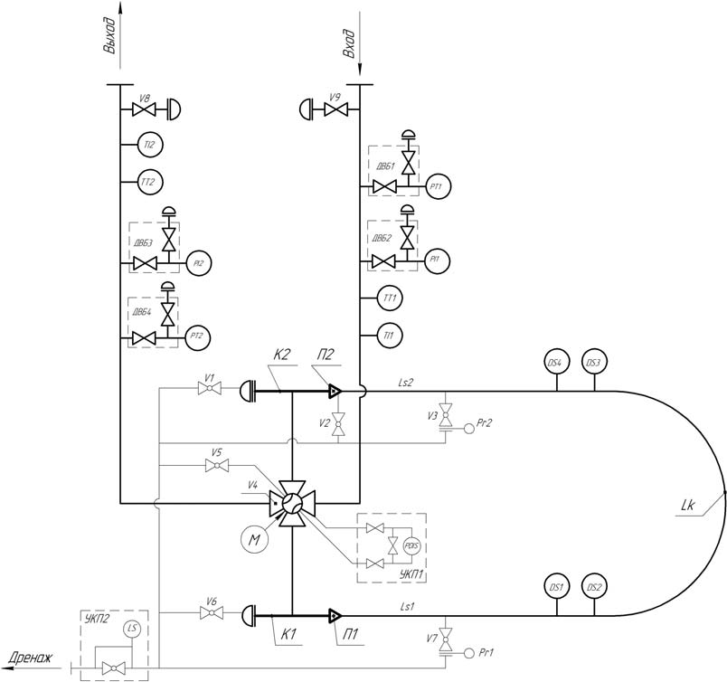
Standard ball prover parameters
| Parameter | PE01 (unidirectional) or PE02 (bidirectional) |
|---|---|
| Nominal capacity of the measuring section, m³ | from 0.1 to 20 |
| Measuring section diameter, mm | from 100 to 900 |
| Relative error, % | ±0.05; ±0.1 |
| Seismic resistance | 9 points per MSK-64 scale |
| Maximum flow rate, m³/h | from 3 to 4000 |
| Min / max flow ratio | 1:20 |
| Version | stationary, mobile |
| Measured medium | oil per GOST R 51858-2002, crude oil, petroleum products, liquefied gases, chemicals, industrial liquids, water |
| Pressure, MPa, not more than | 10 |
| Explosion protection marking | 1Ex IIB T3 Gb X; 1Ex IIB T4 Gb X |
| Medium temperature, °C | from minus 40 to plus 100 |
| Ambient temperature (standard version), °C | from minus 5 to plus 40 |
| Ambient temperature (special version), °C | from minus 60 to plus 54 |
| Power supply parameters | AC voltage 50±1 Hz: 230±10 %; 400±10 % |
| Average service life, years | 25 |
Specific values of the ordered configuration are stated in the product passport.
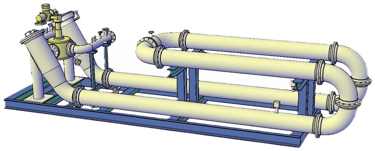
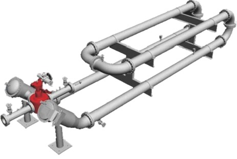
Design examples
Documentation
Selection questionnaire, measuring instrument type description and operation manual.
What works together with the pipe prover
Proving equipment, metering systems and controllers within a metering station.
Need a pipe prover unit for your task?
We will select the size for your flow rate, pressure and site conditions and send a quotation.